I work in a really cool co-working space. Not only can you chat with peeps from other companies while grabbing a cup of coffee, but you can also freely explore all the fun stuff residing in our large communal space. A whole cupboard full of NERF-guns, ping-pong and fusball tables, a VR flight simulator and last but certainly not least – a 3D printer. While the 3D printer is free for everyone to use, the filament belongs to different people in the office. A user must recover the cost of a coil and compensate a small amount for the filament being used in each print. And it was here when I was doing just that I had an idea!
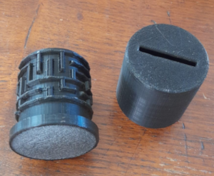
On Thingiverse are several designs for labyrinth gift boxes available as download as *.stl. My idea was to create a similar box, but as a piggy bank for the filament compensation money. But as each coil of filament usually belongs to somebody else, those piggy banks of course also needed to have individual labyrinths.
By this point I knew I was already vastly overthinking it. Not only was the old “just put that money on whoevers desk that you used the filament from” approach working just fine, but also there was no need to make the piggy banks theft proof as no-one in our office would actually steal any money…especially not if that amounts rarely exceeds a dollar.
But by being German, I had a stereotype of over-engineering everything to live up to, so I started designing little boxes with customizable labyrinths on them.
On mazegenerator.net one can create random mazes and download them as *.svg for non-commercial use. This seemed like a good starting point to me. These SVG files contain only straight lines representing the walls of the labyrinth. These lines in a straight plane, let’s call it the  plane with an aspect ratio of
  , need to be mapped onto the cylindrical
  surface. With a given radius
  of the cylinder, the corresponding height
  of the cylinder should be set to
  , so the original labyrinth does not get stretched in either direction on the cylindrical surface. The mapping from the plane onto the cylinder surface can then be defined as
(1) 
Having the coordinates on the cylinder plane, one can easily transform them to cartesian coordinates. A sweep along a line in the plane can so be mapped onto the cylinder surface and then into the three dimensional space.
As we do not only want to imprint the lines onto the cylinder, but also create walls, we additionally need to sweep a profile along those lines. Here, I chose a trapezoid profile with a lower width of  , an upper width of
  and a height of
  . With some slight adjustments for the head and tail end of the sweep, those faces are then also slightly sloped like the sides. Once all those walls are created, one can just unite them with the original cylinder and use that body for further design.
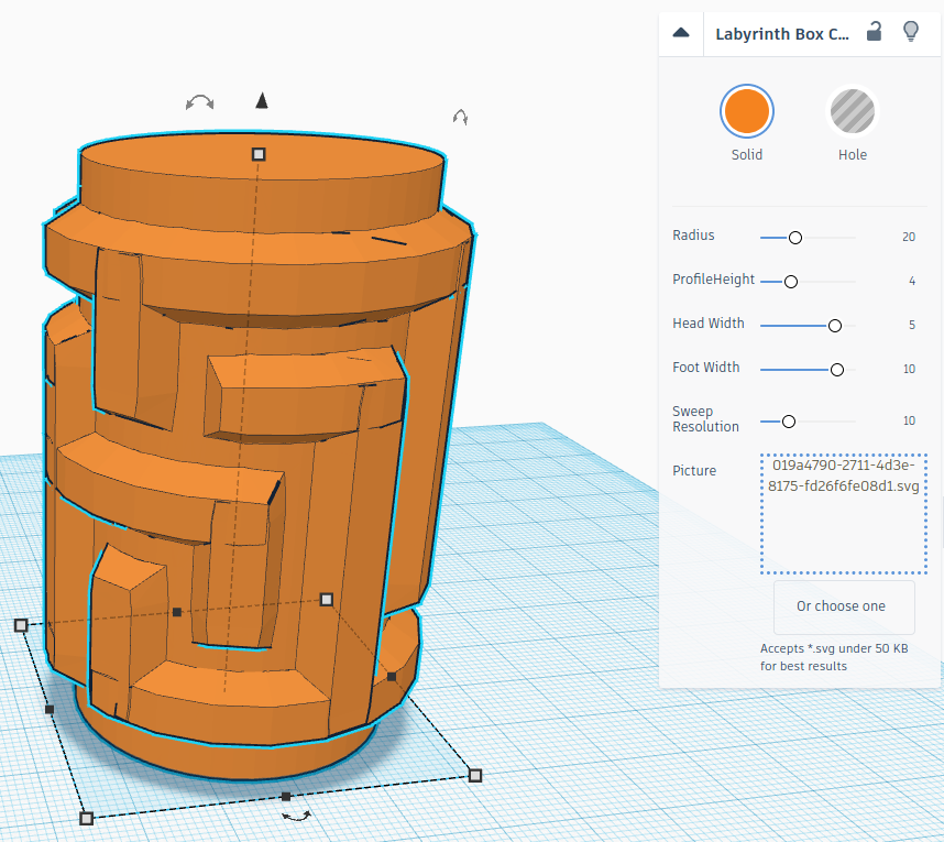
The cylinder shape creator can be found here. Unfortunately, TinkerCAD limits the computational power one can use for shape generators, so bigger labyrinths are only possible with lower resolution or are not possible at all.
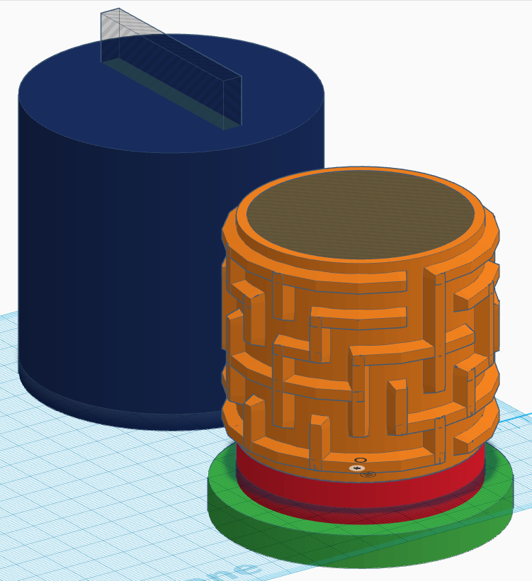
Having that cylinder, one can then build all kinds of items from it. The piggy bank mentioned earlier in this post can be found here. Feel free to use it for any non-commercial usecases!
Labyrinths and their SVGs that have been used for this post are obtained from mazegenerator.net and are free to use for non-commercial use. All pictures and models in this post are are subject to a Creative Commons Attribution-NonCommercial 4.0 International License.